Special Bridge Safety Inspection Technology Utilizing Robots
▲ Senior Researcher Seo Dong-woo, KICT Department of Structural Engineering Research
Prologue
Most of the structures currently constructed as special bridges in Korea (collectively referring to cable-stayed bridges on which the measurement system is built) are constructed in the form of cable-stayed bridges or suspension bridges. Since the service life required for special bridges is more than 100 years, the stability, durability, and usability of the structure must be secured (KSCE, 2006). Damage to cables, which is one of the key deficiencies in special bridges, is a major factor reducing bridge safety and shortening service life. Cable damage is caused not only by environmental factors (climate, load, earthquake, etc.) but also by unpredictable accidents such as fire or collision. If a bridge in public use must suspend its operation due to cable damage, the economic and social losses are enormous (Na et al., 2014). In Korea, there was an accident in which one out of a total of 144 construction materials was completely broken and two were partially damaged by a cable fire at Seohae Bridge (cable-stayed bridge) (Gil et al., 2016).
Although studies aiming to develop various inspection technologies for the safety and maintenance of cables are being conducted, there is a limit to the applicability of these technologies to special bridges, especially to cables, which are large facilities, due to limitations in the mobility and accessibility of equipment. To address this, efforts to develop a cable inspection robot capable of non-destructive testing are ongoing (Kim et al., 2014). To apply the inspection robot to cables, it is necessary to secure its field usability by using a wireless system and minimizing dead-weight.
In this article, I would like to introduce a cable inspection robot equipped with an electromagnetic sensor to improve the driving stability, which was pointed out as a disadvantage of existing inspection robots, and to detect whether the inside of the cable is damaged.
Design and Specifications of Cable Inspection Robot
In making the cable inspection robot, we focused on the applicability of large diameter cables over 200 mm and securing the robot's driving stability. Figure 1 shows the 3D image of the cable inspection robot and its main devices. The dimensions of the robot are 510 mm × 610 mm × 710 mm, and the weight is reduced to 12.8 kg. In addition, to improve durability, the frame of the robot was made of aluminum. A high-resolution IP camera (1920 × 1080 pixels) was installed to take pictures of the exterior of the cable, enabling real-time cable shot images to be transmitted with a wireless Wi-Fi router. Furthermore, the movement distance of the robot could be calculated using an acceleration sensor and a rotary encoder. Three driving motors (IG-32GM, DC12) and urethane wheels were installed so that the robot can move on the cable while minimizing its shaking during climbing. In addition, a variable diameter adjustment part (140-300 mm) was made to improve the adhesion between wheel and cable.
The wireless remote control of the robot uses IEEE 802.11 an/ac 5 GHz 2×2 MIMO to achieve a communication distance of 10 km and a data transmission rate of up to 867 Mbps. Damage to the steel wire of cables is detected with an electromagnetic sensor. As shown in Figure 2, the principle applied is that the polarity is divided again at the damaged area when the cable breaks or gets damaged. As shown in Figure 3, the sensing device mounted on the inspection robot for cable damage detection consists of pipe diameter adjusting units that can be adjusted according to the cable diameter and a roller for moving on the cable surface. Also, the electromagnetic sensor for detecting cable damage is inserted in the middle of the roller part.
Performance Evaluation of Cable Inspection Robot
Indoor and outdoor tests to evaluate the driving performance of the cable inspection robot were conducted as shown in Figure 4. One cable-stayed bridge with a history of cable accidents was selected as a test bed bridge for field tests of bridges currently in public use. The bridge is a short-span earth-anchored steel composite cable-stayed bridge with a span length of 400 m and a width of 23.9 m, on a four-lane road (two ways). The field cable (200 mm) had an inclination angle of 27.3 degrees, and the indoor test was conducted at 45 degrees.
With the verification test, the climbing speed (19 cm/s) and the descent speed (20 cm/s) were evaluated, and it was confirmed that the robot is effectively controlling its speed when the speed increases due to slipping that may occur during the descent. It was also confirmed that the driving speed was constant regardless of the inclination angle. In addition, real-time images of the cable surface were taken with three cameras in the field test, and as shown in Figure 5, it was confirmed that visual inspection of the cable was possible. No communication-related problems occurred during the performance verification test.
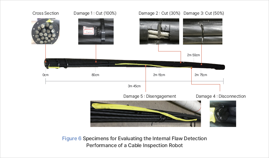
The cable damage detection test was conducted indoors. The cable specimen used in the indoor test is a type of cable currently used in bridges, and the inner cable consists of 20 pieces of one bundle composed of seven 1.57 mm strands. For the cable sheathing, the same High-Density Polyethylene (HDPE) tube used in the driving capability test was used. To detect cable damage, damage types were artificially simulated as shown in Figure 6. Cut damage was subdivided according to the degree of cross-sectional cut into 30%, 50%, and 100% cut (break). For disengagement damage, the case where the cable protruded to the outside in a tidy state was reproduced. For disconnection, one cable was made short.
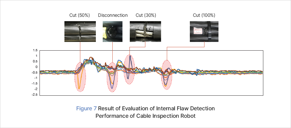
Figure 7 shows the results of the test conducted indoors. In the graph, the X-axis is time and the Y-axis is the electromagnetic sensor measurement. It can be seen that the phase of the electromagnetic sensor measurement changed by 180 degrees at the point where damage (cut) took place. On the other hand, it was confirmed that the phase of the electromagnetic sensor measured value did not change during disconnection, but the magnitude of the magnetic field increased. To secure the reliability of the experimental results, it is considered that additional experiments are needed, with more diverse damage types and repeatability than those conducted in this study.
Epilogue
This article introduced the development of a cable inspection robot capable of measuring large-diameter cables over 200 mm. The developed cable inspection robot has expanded its field applicability by improving its driving ability, driving stability, and wireless communication performance. The possibility of detecting damage to the inside of the cable using an electromagnetic sensor was verified through an indoor test. However, it is considered necessary to further improve inspection efficiency by developing an analysis algorithm that in addition to detecting the presence of cable damage can determine the degree and type of damage through additional tests. If facility maintenance technology using inspection robots is continuously advanced and applied, it is expected that it will greatly contribute to facility safety management. This cable inspection robot was developed with budget support by the Ministry of Land, Infrastructure, and Transport. It has been handed over to the Korea Authority of Land & Infrastructure Safety and is being used for the maintenance of general national highway special bridges.