Development of Visualization Technology for Building Energy Information Based on IndoorGML
Development of Visualization Technology for Building Energy Information Based on IndoorGML
▲ Research Fellow Choi Hyun-sang, Department of Future & Smart Construction Research, KICT
Prologue
In the representation of indoor spaces used in the construction of indoor spatial information, international standards such as IFC (Industrial Foundation Classes), CityGML (City Geographic Markup Language), and IndoorGML (Indoor Geographic Markup Language) can be applied. There are two ways to construct indoor space data using these standards: the first is a direct construction method using authoring programs, which allows for detailed representation but involves a significant amount of time and cost. The second method involves creating data by converting data that are already standard or are used in practice, which is effective in reducing time and cost. Thus, this study aimed at developing a Revit Plug-In based on BIM to extract core indoor spatial information object from sample models, convert them to IndoorGML and integrate them with data visualization technology to develop the supporting technology for the utilization of indoor spatial information.
Theoretical Considerations of IndoorGML
IndoorGML is a data model for expressing and exchanging indoor spatial information, which was developed by the Open Geospatial Consortium (OGC), an international standardization organization for spatial information. It is a data standard in GML format based on XML (eXtensible Markup Language) schema. IndoorGML was developed to support the requirements for indoor spatial data services, and is defined based on a cell space model. IndoorGML focuses on the expression of the geometric relationships and topology (topological relationships) information of indoor spaces, rather than the detailed representation of indoor objects such as building components or furniture. In IndoorGML, the smallest and most basic spatial unit that constitutes a building is called a cell space, and a building is considered a series of cell spaces. To represent this cell space model in detail, IndoorGML defines the following four items:
- Cell Geometry
- Topological Relationship between Cells
- Meaning of the Cell
- Multi-Layer Spatial Model
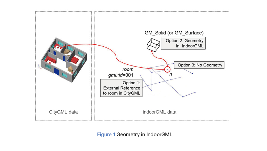
Based on the four definitions mentioned above, IndoorGML can ① represent the characteristics of indoor spaces, and ② provide spatial reference information about the topographic features located within indoor spaces. Figure 1 shows the geometry options provided by IndoorGML. It displays three options for geometric representation in IndoorGML, and the meanings of each option are as follows:
- Option 1 : (External Reference) Instead of explicitly representing geometry in IndoorGML, it can be expressed solely through external links to objects defined in other datasets, such as CityGML.
- OOption 2 : (IndoorGML Geometry Information) When including geometric representations for cell spaces in IndoorGML, 3D spaces are represented as GM_Solid, and 2D spaces (walls) are represented as GM_Surface according to the definition in ISO 19107. Openings (e.g. doors, windows, etc.) are also included in this case.
- OOption 3 : (No Geometry) IndoorGML document does not include geometry information for cell spaces (spaces can be represented solely by Nodes).
Geometry Rules for IndoorGML Conversion
The geometry rules for the key objects that constitute IndoorGML are based on the modeling rules presented in the SIG3D "Modeling Guide for 3D Objects Part 1: Basics (Rules for Validating GML Geometrics in CityGML)" technical document. Among the regulations in the aforementioned technical document, the implementation rules for representative objects that are most closely related to this study are as follows:
- gml : LinearRing: The geometry composing the objects that make up the building is comprised of a single polygon boundary, i.e. a LinearRing (Rs) (Figure 2).
- gml: Polygon: A polygon (S) is represented as a set of planar LinearRings (Rs).
- gml : MultiSurface: The MultiSurface used to visually represent the surface objects (M) that make up a building is represented as a collection of unstructured polygons (S), i.e., M={S1, S2, Sn}.
- gml: The geometry of a 3D object is defined as a collection of polygons that are composed of multiple surface objects (Multi-Surface), and errors can occur depending on the composition of the polygons. Table 1 shows examples of correct and incorrect cases when constructing indoor objects.
Development of IndoorGML Plug-In Based on Revit Software
(1) Design of Revit Data Conversion Process
Autodesk's Revit software, which is commonly used to create 3D BIM models, provides a range of 3D modeling features that support accurate input in terms of visualization and geometry, as well as tools to input and manage relationships between constituent objects. In this study, the Room Schedule and Door Schedule functions provided by Revit were used as a basis, and the CellSpace (Node) and Transaction (Edge), which are core objects of IndoorGML, were constructed based on the connection information entered between the spaces during building design. However, if Room/Door Schedule is missing in the initial BIM modeling process or is omitted due to worker error, it must be checked and corrected through a pre-validation process. Figure 3 shows the data conversion process applied in this study.
(2) How to Use Revit's Room Objects, and Rules for Handling Virtual Spaces
To extract CellSpaces in IndoorGML using Room objects created in Revit, it is necessary to first check whether the Room object has been input into the Revit model. Figure 4 shows that if a Room object has been input, it is displayed on the screen with crosslines, and that even irregular spaces can be configured as Room objects. In the design of typical buildings, only spaces composed of actual structures (walls, columns, floor surfaces, ceiling surfaces, etc.) are represented. However, in IndoorGML, an indoor space information, it is necessary to divide virtual indoor spaces for large spaces such as auditoriums or banquet halls, as well as narrow and long corridors with changing directions. For this purpose, preprocessing of virtual spaces is required before converting to IndoorGML, and setting and modifying rules for processing virtual spaces is necessary. In this study, additional functions were developed based on the features provided by Revit for processing virtual spaces.
(3) Main Features and Achievements of Revit SW-based IndoorGML Plug-In
In the Revit SW, it is common to create Room and Door Schedules during the BIM modeling process. However, there may be cases in which they are omitted due to human error or spatial constraints, so it is necessary to check them in advance and make corrections as needed. Figure 5 shows a feature provided by Revit that allows the user to check Room Tags and missing information. Then, when converting Revit data to IndoorGML data using the "IndoorGML Exporter" menu, a verification process is also carried out to check for any missing information. Once the verification of the Revit data that serves as the source of IndoorGML is complete, the user can selectively convert only the desired floors or the entire building into a single IndoorGML file. Figures 7 and 8 show examples of the conversion of Main Buildings 1 and 2 of the Korea Institute of Civil Engineering and Building Technology (KICT).
(4) Development of IndoorGML-based Building Energy Information Visualization System
In this study, we developed a 3D system that can visualize building energy management by assigning representative values for each spatial unit based on measured values by room and location in Main Building 1 of KICT that was investigated through the aforementioned process, as well as values obtained from the survey. Figure 9 shows the process of integrating the results of a user satisfaction survey program for the building, KBOSS, into indoor space units (left), and examples of floor-by-floor visualization (right).
Epilogue
This study was performed to secure the core technology for integrating and managing detailed energy data for individual building units and occupant satisfaction survey results in a format that is compliant with the international spatial information standards, which is necessary for developing the technology for energy inspections of metropolitan-scale buildings. Through this study, an IndoorGML data authoring tool was developed and applied to store and represent energy-related information investigated for KICT at the minimum space unit (room) level. It is expected that the results can be utilized as a database and operational technology for micro-level building energy inspection information in the future implementation of carbon reduction policies, which are an important part of building energy monitoring and management on a national scale.